
Required special tool
- Fre. 244-03, Fre. 1085-01 Manometer for checking the performance of the brake force regulator.
- Roulette (used to measure the height of the control points under the car).
These vehicles are equipped with brake force regulators. Pressure readings are taken with a diagonal separation of the brake circuit by comparing the pressure in the rear wheel circuit with the pressure reported to the front wheel circuit.
The dual-circuit brake force regulator has two completely separate brake force regulators with their own housings, which, with a diagonal separation of the brake circuit, act on the circuit of one front and one rear wheel.
Table 1.11
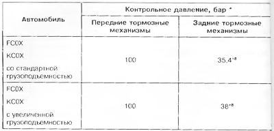
* Check is carried out with a full fuel tank (driver in car).
* The test is carried out with two pressure gauges placed diagonally according to the diagonal division of the brake circuits.
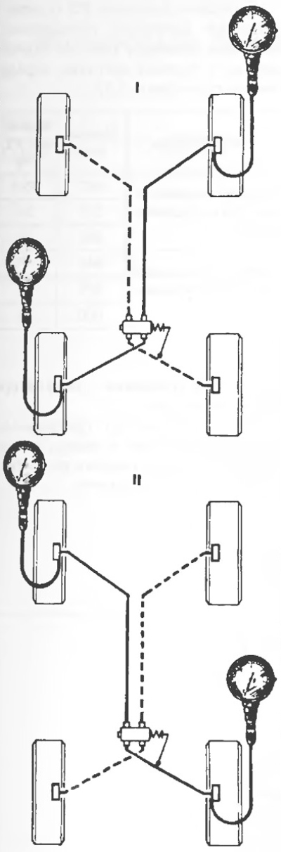
Pic. 1.19.
Both circuits must be checked.
I: front right wheel/rear left wheel;
II: front left wheel/rear right wheel.
Note. The brake force regulators differ depending on the type of rear axle:
- - rear axle of normal load capacity: red mark;
- - heavy-duty rear axle: green mark.
Examination
1. Connect two pressure gauges Fre. 244-03 or Fre. 1085-01:
- one at the working cylinder of the front right wheel;
- the other at the working cylinder of the rear left wheel.
2. Depressurize the pressure gauges using the P nut.
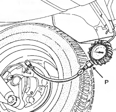
Pic. 1.20
3. Gradually depress the brake pedal until the required pressure is established in the front wheel circuit (tab. 1.11). Read the pressure reading and, if necessary, correct it in the rear wheel circuit.
4. Perform the same operation on the other circuit:
- one pressure gauge at the working cylinder of the front left wheel;
- another pressure gauge at the working cylinder of the rear right wheel.
5. If there is a big difference (values exceed tolerance), then replace the brake force regulator, since it cannot be repaired.
Adjustment 1
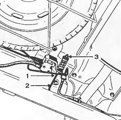
Pic. 1.21
1. Checking and adjustment is carried out on an unladen vehicle with a full fuel tank with a driver at the wheel.
After reaching a certain pressure in the front wheel circuit as a result of pressing the brake pedal, immediately record the pressure in the rear wheel cylinder circuit and compare with the control values (tab. 1.11).
2. Move the pressure lever, loosening the nut 1 until the lever 2 can be moved.
Attention! Do not change the position of the nut 3.
Adjustment 2
1. Car preparation:
- the car must be left loaded;
- the person who is obliged to press the brake pedal while adjusting the brake force regulator must be in the car when measuring the rolling radius of the rear wheels under load;
- The vehicle must be parked on a flat, level, clean and level surface (use a four-post lift if possible).
2. Marking the centers of the rear wheels:
- Raise the rear of the car just enough to allow the rear wheels to turn
- touch with a piece of chalk the wheel cap or decorative false pack approximately in the center of the wheel;
- turn the wheel fast enough with your hand and at the same time firmly press the piece of chalk.
This will draw concentric circles around the actual center of rotation of the wheel.
- highlight the center with a chalk pencil;
- do the same operation on the other rear wheel.
3. Adjusting the air pressure in the tires of the rear wheels:
- air pressure must be adjusted on the wheels standing on the floor and when a person is at the driver's workplace;
- reduce the air pressure in the tires of both rear wheels to 1.2 bar (use an accurate pressure gauge);
- wait a few minutes for the air in the tires to warm up to ambient temperature, as the air cools as it is released from the tire and the tire pressure changes;
- bring the pressure to 1.2 bar as accurately as possible.
4. Measurement of the wheel rolling radius on an unloaded vehicle:
- raise the rear wheels so that they no longer deform under the load on the rear axle (until the wheels are off the floor);
- Measure the distance from the floor to the center of the wheel with a tape measure.
5. Measurement of the wheel rolling radius on a loaded vehicle:
- put the car on wheels;
- Measure the distance from the floor to the center of the wheel with a tape measure.
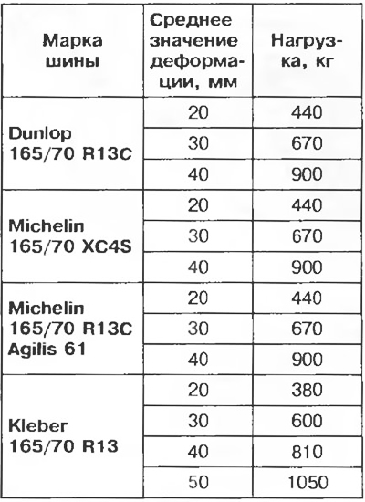
6. Determination of tire deformation:
- determine the difference between the results of both measurements to obtain the amount of tire deformation.
7. Follow steps 4, 5 and 6 for the other rear wheel.
8. Determine the average deformation for both tires:
- add the deformation values determined for the two rear wheels and divide the result in half to find the average deformation value.
Rear axle load as a function of the determined average tire deflection.
Table 1.12
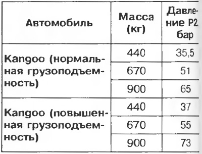
Outlet pressure P2 (corresponding to the pressure reported to the working cylinder of each rear wheel) in the load function determined according to table 1.12.
9. Adjusting the brake force regulator:
- follow the method suggested to be carried out during operation if the adjustment of the brake force regulator is disturbed.