



Contents: Control axis 🠛 Installation of shafts 🠛
Control axis
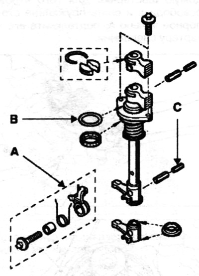
The control axis is provided with a shut-off valve attached to the crankcase A. Sealing is ensured by the sealing ring B.
After removing the selector lever C pins, remove the mounting bolts and control assembly.
Installation of shafts
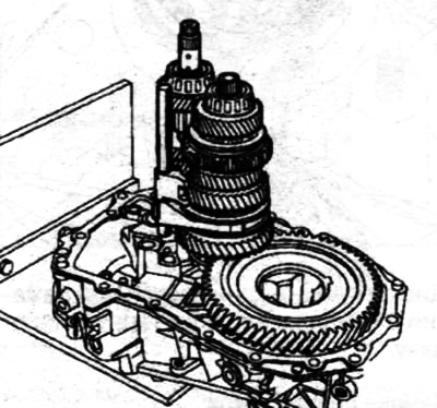
Install the primary shaft and secondary shaft with the ½ fork at the same time.
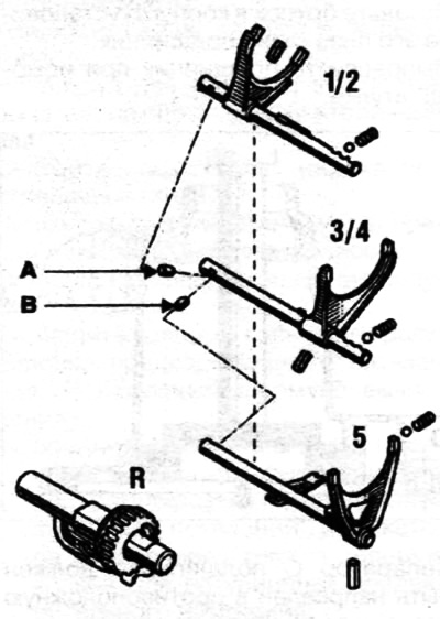
Install the ½ gear rod lock pin A and the 5th gear rod lock pin B.
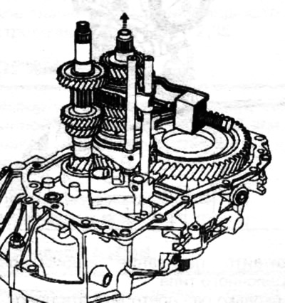
Raise the 3/4 hub slightly and install the 3/4 fork and stem.
 |
 |
 |
 |
Insert the pins into the fork using tool B. Vi. 949.
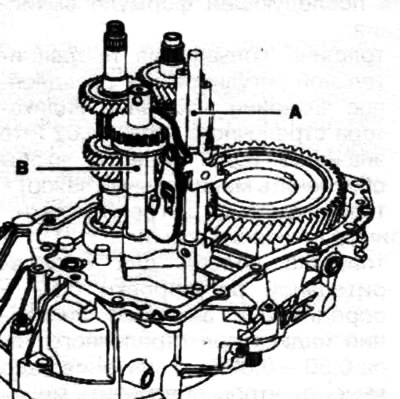
Install the fifth gear rod A and the reverse axle B. To do this, slightly raise the input shaft.
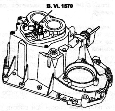
Install the springs and balls for the ½ and 3/4 lock into the crankcase and compress them using the tool B. Vi. 1570.
Apply Loctite 518 to the joint surface.
Set to third gear.
Position the crankcase with the control shaft in third gear and install the spring and ball to lock until the fifth gear rod appears.
Compress the ball to lock and finish installing the crankcase.
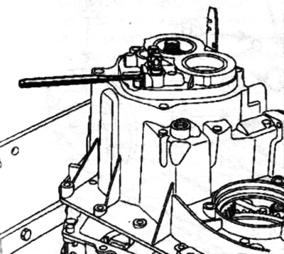
Remove tool B. Vi. 1570. Turn the input shaft to correctly install the bearings and tighten the tightening bolt to torque (25 Nm).
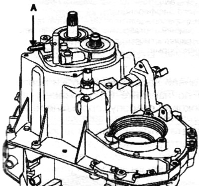
Install the reverse axle A into place.
Apply three drops of Loctite Frenbloc to the splines of the constant mesh gear and install it using tool B. Vi. 1175.
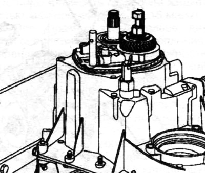
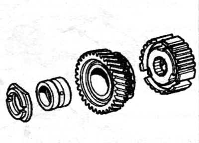
On the primary shaft install:
- support ring (with the larger side facing the gear);
- bushing under the gear;
- fifth gear parasitic gear equipped with a synchronizing ring;
- fifth gear hub with spring.
 |
 |
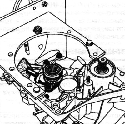
Using tool B. Vi. 31-01 (punch), install the fifth gear fork pin.
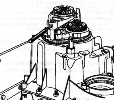
Engage first gear with the gear shift lever and fifth gear by sliding its fork along the rod.
Tighten the bolt and nut of the gears to the torque:
- primary shaft nut - 25 Nm;
- secondary shaft bolt - 160 Nm.
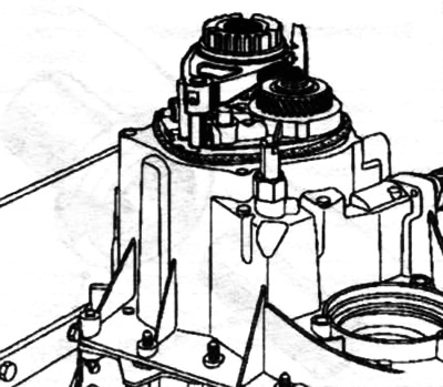
Set the gearbox to neutral.
Install a new O-ring.
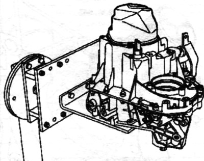
Install the back cover and tighten the bolts to torque (25 Nm).
 |
 |
Reinstall the reverse contactor.
Install the JH semi-automatic transmission speed sensor in place.
Install the clutch release slave cylinder and tighten the bolts to 21 Nm.
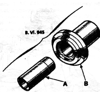
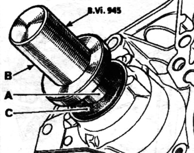
Install the differential output shaft seal using tool B. Vi. 945.
Place the oiled safety sleeve A on the planetary gear and fit the oiled seal C using tool B.
 |
 |