



Contents: CV joint G162 🠛 CV joint RC490 🠛
1. Remove the drive shaft as described in Chapter 2.
2. These models use two different types of inner CV joints: G162 and RC490. The CV joints can be distinguished by the shape of their housing. The G162 has a smooth, rounded body, while the RC490 has a sculpted body (its cross-section is shaped like a trefoil).
CV joint G162
Note: A suitable repair kit of parts is required.
3. Release the large retaining spring and inner locking ring, then slide the boot down the shaft to access the CV joint.
4. Using pliers, carefully bend back the corners of the locking tabs of the fastening plate (see illustration).
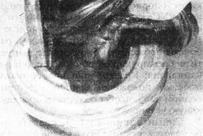
4.4 Bend back the locking tabs with pliers to release the G162 CV joint housing.
Slide the CV joint housing off the tripod. Keep the tripod rollers in the working position, otherwise they may jump off their supports, with which they form coordinated pairs (that's why they can't be swapped). If necessary, secure the rollers with adhesive tape.
5. Using special pliers, remove the retaining ring securing the tripod CV joint to the drive shaft (see illustration).
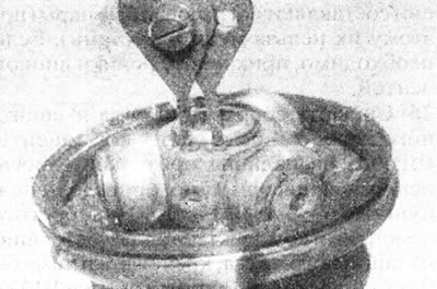
4.5. Remove the retaining ring...
Please note that on some models the CV joint may be secured with a locking rim that must be bent back with a file. Mark the position of the clutch in relation to the drive shaft using paint or a punch.
6. Remove the CV joint tripod (see illustration).
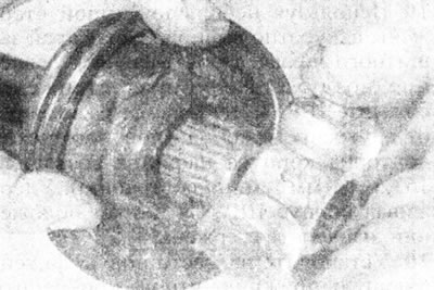
4.6. ...and remove the tripod from the end of the drive shaft.
If this fails, use a puller to pull it off the end of the drive shaft. Make sure the puller feet are positioned behind the tripod and do not touch the rollers. Alternatively, support the tripod and press the shaft out of it using a hydraulic press, again being careful not to let the tools touch the rollers.
7. Remove the protective boot and inner locking rim from the end of the drive shaft.
8. Wipe the CV joint components clean, being careful not to remove the alignment marks made during removal. Do not use kerosene or other solvents to clean this type of hinge.
9. Inspect the tripod, rollers and CV joint housing for scuffs and signs of wear. Make sure the rollers rotate easily on the tripod supports. If wear is evident, the tripod and roller assembly can be replaced, however, the CV joint housing is not sold separately. Purchase a new protective cover, retaining spring/collar and special grease.
10. Tape the grooves at the end of the drive shaft, then carefully install the inner locking rim and protective boot onto the shaft.
11. Remove the tape, then, aligning the marks made during removal, install the tripod onto the grooves of the drive shaft. Use a hammer and a soft metal drift to drive the tripod into position on the shaft. Be careful not to damage the drive shaft grooves or the hinge rollers. Alternatively, clamp the drive shaft and drive the tripod into position using a hydraulic press and a suitable hollow spacer.
12. Secure the tripod CV joint with the snap ring, making sure it fits into the groove of the drive shaft. Where a snap ring is not used, attach the CV joint by bending the edge of the drive shaft with a hammer and punch at three points 120° apart.
13. Evenly distribute the grease contained in the repair kit around the tripod and inside the CV joint housing. Fill the protective boot with the remaining grease.
14. Install the CV joint housing in the working position on the tripod.
15. Make a support plate from a piece of steel or similar sheet 2.5 mm thick (see illustration).
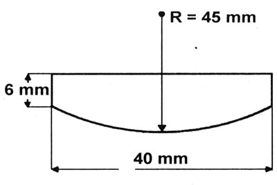
4.15. Homemade support plate for bending the locking tongues - CV joint G162.
16. Using a hammer, place a plate under each of the CV joint housing locking tabs one by one and bend their corners down onto the support plate, then remove the plate.
17. Replace the protective cover. Place its edges into the grooves of the drive shaft and CV joint housing.
18. Install the inner locking rim into the working position on the inner end of the protective boot.
19. Using a small blunt stick, gently lift the edge of the protective cover to equalize the air pressure. Without removing the rod, compress the CV joint so that the distance from the inner end of the protective cover to the end of the joint housing is 153.5±1 mm (see illustration).
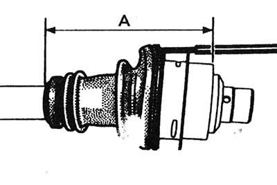
4.19. Correct location of the protective boot of the inner CV joint of the right drive shaft - CV joint G162. A = 153.5±1 mm
While holding the CV joint housing in this position, remove the rod.
20. Install the new retaining spring to secure the outer edge of the boot to the hinge housing.
Try not to overstretch the spring during installation.
21. Make sure that the CV joint moves freely in all directions, then install the drive shaft (see Chapter 2).
CV joint RC490
Note: A suitable repair kit of parts is required.
22. Using pliers, bend up the metal cover of the joint at the points where it is driven into the recesses of the CV joint housing (see illustration).
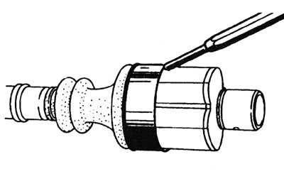
4.22. Remove the metal cover from the inner CV joint of the right drive shaft - CV joint RC490.
23. Cut the inner clamp of the protective cover with nippers.
24. Using a soft metal drift, knock the metal cover off the CV joint housing. Slide the joint housing off the CV joint tripod. Keep the tripod rollers in the operating position, otherwise they may slip off their bearings, which they pair with (that's why they can't be swapped). If necessary, secure the rollers with adhesive tape.
25. Remove the tripod and boot assembly and inspect the CV joint components for signs of wear, using the information provided in paragraphs 6-9 of this Chapter. Obtain a repair kit consisting of a boot, mounting clamp, metal insert, CV joint cover, and special grease.
26. Install the metal insert into the inside of the boot, then place the boot assembly inside the metal CV joint cover.
27. Wrap the grooves of the drive shaft with adhesive tape and install the boot and CV joint cover assembly on the shaft.
28. Install the tripod as described in points 11 and 12.
29. Evenly distribute the special grease contained in the repair kit around the tripod and inside the CV joint housing. Fill the protective boot with the remaining grease.
30. Install the CV joint housing into the working position.
31. Slide the metal CV joint cover onto the joint housing until it is flush with the housing guide. Attach the cover by driving it into the recesses of the CV joint housing using a hammer and a punch with a rounded end.
32. Using a small blunt stick, gently lift the inside edge of the protective boot to equalize the air pressure. Without removing the rod, compress the CV joint so that the distance from the inner end of the protective cover to the end of the joint housing is 156±1 mm (see illustration).
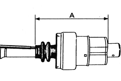
4.32. Correct location of the protective boot of the inner CV joint of the right drive shaft - CV joint RC490. A = 156±1 mm.
While holding the CV joint housing in this position, remove the rod.
33. Install the smaller clamp onto the inner end of the protective boot. Tighten the clamp by gently squeezing the raised portion. If you don't have a special tool, you can use pliers.
34. Make sure that the CV joint moves freely in all directions, then install the drive shaft as described in Chapter 2.