



Note: A suitable repair kit of parts is required.
1. Remove the drive shaft as described in Chapter 2.
2. Using special pliers, remove the retaining ring securing the CV joint tripod to the drive shaft. Please note that on some models the CV joint may be locked in the working position; in this case, release the locking rim using a file. Use paint or a punch to mark the position of the tripod on the drive shaft to facilitate subsequent installation.
3. Remove the tripod. If this fails, use a puller to pull it off the end of the drive shaft. Make sure the puller feet are positioned behind the tripod and do not touch the rollers. Alternatively, support the tripod and press the shaft out of it using a hydraulic press, again being careful not to let the tools touch the rollers.
4. The protective boot/bearing assembly is removed in the same manner. Remove the mounting plate, remembering its correct location.
5. Purchase a new protective cover that comes with a small bearing.
6. The bearing and protective cover must be driven into working position, preferably using a press. When using a hammer and a tubular drift, there is a high risk of deformation of the bearing seal.
7. Install the mounting plate onto the drive shaft, making sure it is oriented correctly.
8. Secure the drive shaft and use a press to install the bearing of the protective boot onto it, using a hollow spacer lining that rests only on the inner ring of the bearing. Position the bearing so that the distance from the end of the drive shaft to the inner surface of the bearing is 148.5 mm (see illustrations).
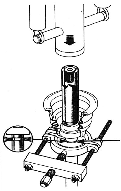
5.8a. Press the protective boot/bearing onto the end of the left drive shaft.
(Original publication on the portal: «renaultbook.ru»)
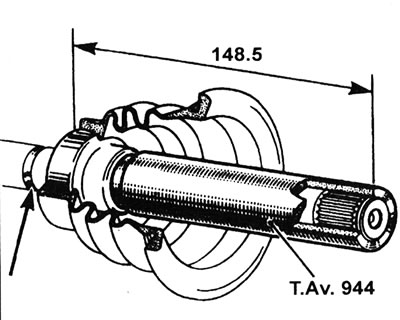
5.8b. Correct location (in mm) of boot/bearing on inner end of left drive shaft.
9. Install the CV joint tripod onto the drive shaft grooves, using the marks made during removal as a guide. Use a hammer and a soft metal drift to drive the tripod onto the shaft. Be careful not to damage the drive shaft grooves or CV joint rollers. Alternatively, secure the drive shaft and install the tripod onto it using a press and a hollow spacer.
10. Secure the tripod with the retaining ring, making sure it fits into the groove of the drive shaft. Where a snap ring is not used, attach the CV joint by bending the edge of the drive shaft with a hammer and punch at three points 120° apart.
11. Install the drive shaft (see Chapter 2).