



Contents: Ball joint 🠛 Universal CV joint 🠛
1. Remove the drive shaft as described in Chapter 2.
2. Cut the protective cover fastening clamps, or release the retaining spring and inner flange (depending on the model), then slide the boot down the shaft to access the outer CV joint.
3. Remove as much grease as possible from the joint and determine the CV joint type.
Ball joint
Note: A matching repair kit of parts is required.
4. Using special pliers, spread the inner CV joint retaining ring. At the same time, tap the visible surface of the joint housing with a mallet to separate the CV joint from the drive shaft. Remove the protective cover and rubber flange.
5. Clean the CV joint using kerosene or a suitable solvent and dry it thoroughly. Inspect the CV joint components.
6. Move the CV joint cage from side to side to gain access to each ball in turn. Inspect the balls for cracks, flat spots and surface pitting.
7. Inspect the ball races on the CV joint housing and in the race. If the races have widened, they will no longer fit tightly around the balls. At the same time, check the CV joint separator slots for cracks and signs of wear.
8. If inspection reveals that any of the CV joint components are worn or damaged, the entire drive shaft assembly must be replaced, as none of the components are sold separately. If the CV joint is in good condition, purchase a repair kit consisting of a new protective boot, rubber flange, retaining spring and grease.
9. Wrap the grooves at the end of the drive shaft with adhesive tape, then install the rubber flange and protective boot onto the shaft. Place the inner end of the boot on the drive shaft and secure it with the rubber collar.
10. Remove the tape, then install the CV joint on the drive shaft so that the inner snap ring fits into the groove of the shaft.
11. Make sure the snap ring holds the CV joint securely, then fill the joint with grease. Spread the lubricant along the ball tracks and fill the protective cover with excess lubricant.
12. Install the outer lip of the protective boot into the groove on the CV joint housing. Lift the edge of the boot to equalize the air pressure. Attach the cover with a large retaining spring, using two pieces of hollow metal tubing to push it apart (see illustration).
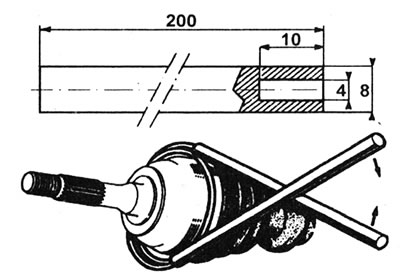
3.12. Install the protective cover retaining spring using two pieces of hollow metal tube. Dimensions are given in mm.
13. Make sure that the CV joint moves freely in all directions, then install the drive shaft on the vehicle (see Chapter 2).
Universal CV joint
Note: A suitable repair kit of parts is required.
14. Remove the inner CV joint, bearing and protective cover (where available), as described in Chapter 4 or 5 this Section.
15. Where the vibration damper is installed, mark its position on the drive shaft, then use a puller or press to remove the vibration damper from the inner end of the drive shaft, remembering its orientation (see illustration).
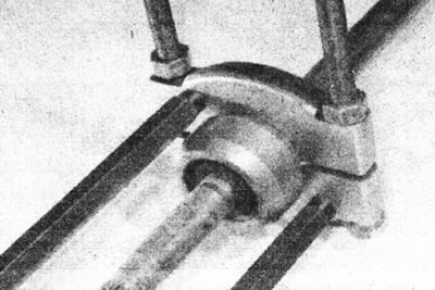
3.15. Remove the vibration damper from the drive shaft.
Make sure that the puller feet or press platen contacts only the inner rubber bushing of the vibration damper, otherwise the vibration damper will deform, which will damage the outer metal casing.
16. Remove the outer CV joint protective boot from the inner end of the drive shaft.
17. Clean the outer CV joint using kerosene or a suitable solvent and dry it thoroughly. Inspect the CV joint components.
18. Check the drive shaft crosspiece and CV joint housing for signs of wear, pitting, and abrasions on their working surfaces. Also make sure that the CV joint housing turns easily and without jerking.
19. If damage or signs of wear are found during inspection, the complete drive shaft assembly must be replaced, as none of its components are sold separately. If the CV joint components are not damaged, purchase a repair kit consisting of a new protective boot, mounting clamps and grease (see illustration).
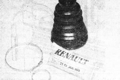
3.19. Branded repair kit of parts for replacing the protective cover.
20. Tape the grooves on the inner end of the drive shaft, then carefully install the outer boot onto the shaft.
21. Fill the CV joint with grease from the repair kit. Distribute the grease thoroughly between the hinge components and fill the protective boot with excess grease (see illustration).
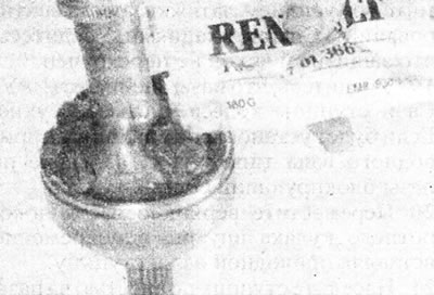
3.21. Fill the CV joint with the grease included in the repair kit...
22. Install the protective boot on the CV joint and make sure that its sealing edges fit into the grooves on the drive shaft and on the joint housing (see illustration).
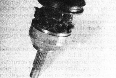
3.22. ...then slide the protective cover into the working position.
Lift the edge of the cover to equalize the air pressure.
23. Install the large metal mounting clamp onto the cover. Tighten the clamp by gently squeezing the raised portion. If you don't have a special tool, you can use pliers. Secure the smaller clamp using the same method (see illustrations).
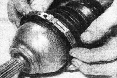
3.23a. Install a large...
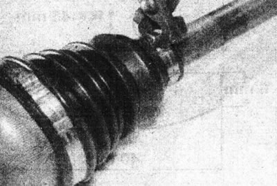
3.23b....and small clamps and clamp them with pliers.
Make sure the CV joint moves freely in all directions before proceeding.
24. Before installing the vibration damper (where available), lubricate the drive shaft with soapy water. Drive the vibration damper into position on the shaft using a hollow spacer that rests only on the inner bushing of the vibration damper (follow the marks made before removal).
25. Install the inner CV joint components as described in Chapter 4 or 5, then install the drive shaft (see Chapter 2).