



2. Most of the actions included in this Part are based on the condition that the engine is installed in the vehicle. Therefore, if this information is used when rebuilding an already removed engine, many of the procedures described here can be skipped.
Engine - general description
3. All F-series engines are 4-cylinder, in-line designs and are mounted transversely at the front of the vehicle. F3P engines have a single overhead camshaft (8 valves), and F7P engines have two overhead camshafts (16 valves) (see illustration).
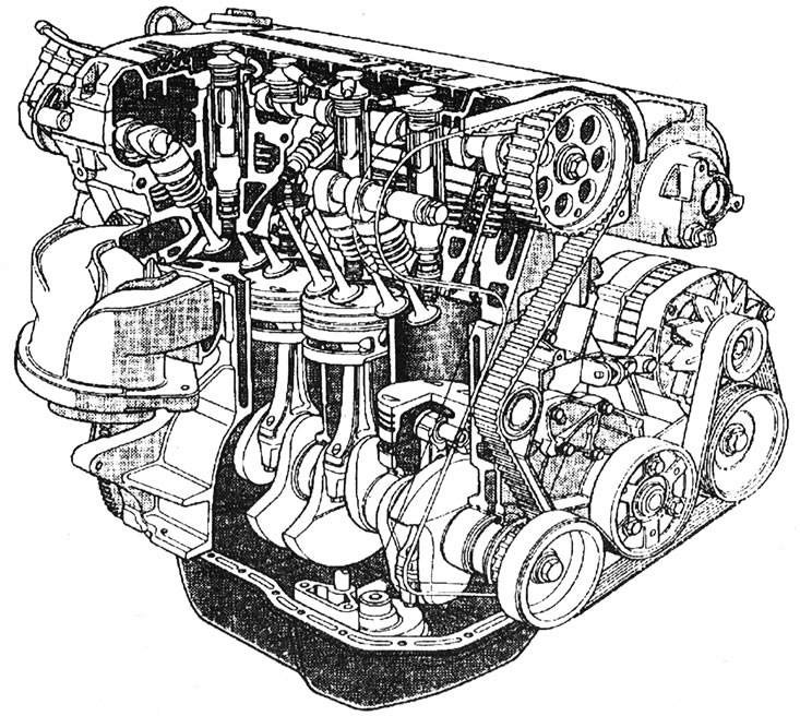
1.3. General view of the F7P engine of the F series (with 16 valves).
4. The crankshaft is supported in the cylinder block on five main bearings. Thrust washers are installed in main bearing No. 2, regulating the axial clearance of the crankshaft.
5. The connecting rods are secured to the crankshaft by means of connecting rod bearings with liners, and to the pistons by means of piston pins, which are fixedly seated in the connecting rods. Piston pins are pressed into the connecting rods on all engines except the F7P (16 valves), in which they float, secured by retaining rings. The pistons are made of aluminum alloy and are equipped with three rings, two compression rings and one oil scraper ring.
6. The camshaft is installed directly in the cylinder head and is driven by a toothed belt from the crankshaft.
7. On F3P engines, the camshaft controls the valves via tappets with an adjusting washer. Adjustment of the valve clearance is carried out by selecting the thickness of the washer installed between the tappet and the working projection of the cam. The intake and exhaust valves are mounted vertically in the cylinder head and each of them is closed by a single spring.
8. On the F7P engine (16 valves), the camshaft controls the valves through hydraulic tappets. The valve clearance is adjusted automatically. The intake valves are angled toward the front of the engine and are controlled by the front (intake) camshaft. The exhaust valves are angled toward the rear of the engine and are controlled by the rear (exhaust) camshaft. Each cylinder has four valves: two intake and two exhaust, which open and close in pairs.
9. On all engines except the late F3P, an intermediate shaft is installed next to the crankshaft, also driven by a toothed belt. The intermediate shaft drives the oil pump via a helical gear. On later F3P engines there is no intermediate shaft (there is only a toothed belt roller sprocket, which takes the place of the intermediate shaft sprocket), and the oil pump is driven by a chain from the crankshaft (see illustration).
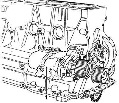
1.9. On late F3P engines there is no intermediate shaft and its casing (1) is removed from the cylinder block.
10. A semi-closed crankcase ventilation system is used. Crankcase gases are drawn from the oil separator on the cylinder block and pass through a hose to the intake manifold.
11. Lubricant is supplied to the engine under pressure created by a gear-type oil pump installed below the crankshaft. Engine oil is supplied through an externally mounted oil filter to the main oil gallery, which serves the crankshaft, intermediate shaft, and camshaft. On the F7P engine, oil jets at the bottom of the cylinders inject oil into the pistons for cooling purposes (see illustration).
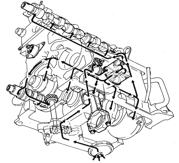
1.11. Lubrication chain on the F3P engine.
Original of this article on the website: renaultbook.ru
12. The distributor rotor is driven directly from the camshaft (on F7P engines from the exhaust camshaft).
Repair operations performed without removing the engine from the vehicle
13. The following actions can be performed without removing the engine from the vehicle:
- Removal and installation the cylinder head.
- Removal and installation the toothed drive belt and sprockets.
- Replacing camshaft seals.
- Removal and installation camshaft(s).
- Removal and installation the pallet.
- Removal and installation of connecting rods and pistons. *
- Removal and installation the oil pump.
- Replacing crankshaft seals.
- Replacing engine mounts.
- Removal and installation the flywheel (on models with automatic transmission, the engine must be removed - see Part F of this Section).
*Note: Although the steps marked with an asterisk can be performed on the engine in a vehicle (after removing the pallet), it is still better to do this with the engine removed. For this reason, these procedures are described in Part F of this Section.