



Basic procedure
2. Disconnect both cables from the battery (start with the negative).
3. Apply the handbrake, then jack up the front right side of the car and support it on axle stands. Remove the right wheel.
4. Remove the plastic cover from inside the right wheel arch to gain access to the crankshaft pulley bolt. On the F7P engine (with 16 valves), unscrew and remove the lower drive cover, which completely covers the pulley.
5. Remove the spark plugs as described in Section 1.
6. Cover the hole of spark plug No. 1 in the cylinder head with your finger (closest to the flywheel). Turn the crankshaft clockwise using the crankshaft pulley bolt until you feel pressure in the cylinder. On the F7P engine (with 16 valves), due to the deep recess for the spark plug in the cylinder head, it is impossible to close the hole with a finger; use a wooden plug for this.
7. Remove the air cleaner assembly as described in the relevant Section Section 4.
8. Looking through the hole on the flywheel, continue to turn the crankshaft until the TDC timing mark on the flywheel aligns with the TDC mark on the clutch housing.
Camshaft sprocket timing marks
9. To view the camshaft sprocket timing marks, do the following. On F3P engines, remove the screw and plastic cover from the top of the right engine mount.
10. On the F7P engine (with 16 valves), remove the plastic cover from the right engine mount, then support the engine with a jack; remove the engine mount bracket and upper drive belt cover/engine mount from the cylinder head.
11. Make sure that the TDC marks on the sprocket (or stars) camshafts are aligned with the TDC mark on the rear cover of the toothed drive belt or on the end of the valve cover (see illustration).
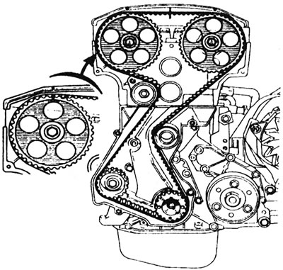
3.11. TDC mark on camshaft sprockets - F7P engine (with 16 valves).
12. If you now remove the distributor cap, the rotor should be facing the toothed segment of the high tension wire of spark plug No. 1.
TDC installation plug
13. The crankshaft can be locked in the TDC position as follows.
14. Remove the plug on the underside of the front engine cover, flywheel side, and prepare a metal rod that should fit exactly into the plug hole. While slightly rotating the crankshaft in different directions, insert the rod through the hole so that it can enter the groove in the crankshaft counterweight (see illustration).
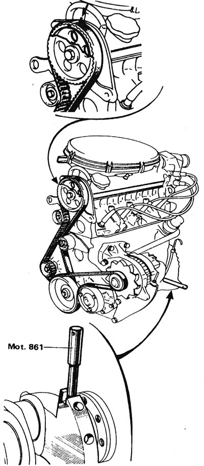
3.14. Locking the crankshaft at TDC - F3P engine.
Make sure the crankshaft is exactly set to TDC for piston #1 (the installation notch on the flywheel must be aligned with the corresponding mark on the clutch housing). If the crankshaft is not positioned accurately, the rod may enter the balancer hole in the crankshaft counterweight instead of the TDC slot.