



Contents: Description 🠛 Examination 🠛
Description
1. The system consists of glow plugs screwed into swirl chambers, a control unit mounted on the bulkhead in the engine compartment, and a coolant temperature sensor attached to the thermostat housing.
2. The glow plugs are powered by the control unit, which also controls the fast idle solenoid valve (on models with air conditioning) and exhaust gas recirculation valve (see illustration).
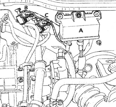
1.2. Pre-start and post-start heating control unit (A), fast idle speed control solenoid valve (B) and exhaust gas recirculation valve (C) (models with air conditioning).
The pre-heating and post-heating stages are controlled as follows.
3. The pre-heating stage is divided into two phases. The first phase, during which the control lamp on the instrument panel lights up and power is supplied to the glow plugs, depends on the coolant temperature. (If the coolant temperature sensor is defective, the spark plugs are automatically energized for 14 seconds.) In the second phase, after the indicator lamp goes out, power is supplied to the glow plugs for another 8 seconds, or until the engine starts. The glow plugs are supplied with power continuously while the starter is running.
4. The post-start heating stage is also divided into two phases. In the first phase, after the engine starts, all glow plugs receive power for an additional 10 seconds. In the second phase, power supply depends on the coolant temperature and engine load. Post-heating is temporarily stopped if the control unit receives a "maximum load" signal from the microswitch on the fuel pump; and resumes if the microswitch contacts open again. After-heating is switched off completely when the coolant temperature reaches 65°C, or after 30 seconds if the coolant temperature sensor is defective.
Examination
5. When a malfunction occurs in the system, checking its serviceability ultimately comes down to replacing it with known good units, but some preliminary checks can be performed as follows.
6. Connect a voltmeter or 12-volt test light between the glow plug supply cable and ground (engine or car body).
7. Have an assistant turn on the ignition and make sure that power is supplied to the glow plugs. Note the amount of time the indicator light remains on and the total amount of time the voltage is applied before the system shuts off. Turn off the ignition.
8. At a temperature in the engine compartment of 20°C, the average time should be as follows: the control lamp should light for 5-6 seconds, and after it goes out, power should be supplied to the spark plugs for another 4-5 seconds (if the starter is not turned on). The indicator lamp will burn longer at lower temperatures, and vice versa.
9. If there is no power at all, the relay or associated wiring is faulty.
10. To identify a faulty glow plug, disconnect the main supply cable and attach a piece of wire to the center terminal of the glow plug. Be careful not to drop the nuts and washers.
11. Check the resistance between each glow plug terminal and ground. The resistance of a good glow plug is very low (less than 1 ohm), and if the tester shows high resistance, the glow plug must be replaced.
12. If an ammeter is available, the current drawn by each glow plug can be measured. After the initial surge of 15-20 A, the spark plug should draw about 10 A. If the spark plug draws much more or much less current, it is probably defective.
13. For a final check, the glow plugs can be removed and inspected as described in Chapter 2.
14. If a control unit malfunction is suspected, the next steps depend on which of the following symptoms are present:
- The heating indicator light on the instrument panel does not work.
- The heating indicator lamp comes on briefly.
- No fast idle mode when the engine is not warmed up (models with air conditioning).
- The engine is malfunctioning (hard to start from cold, runs rough after starting).
(You can find the original at this link Renaultbook.ru)
15. If the heating indicator lamp does not light, disconnect the connector "C" of the control unit. Short the test lamp connector (contact B3/Tem) with ground using a 2A fuse (see illustration).
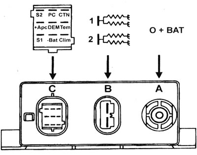
1.15. Pre-start and post-start heating control unit: Battery A+ connector: constant power supply. Connector B: 1 - Power supply for glow plugs 1 and 3; 2 - Power supply for glow plugs 2 and 4. Connector C: A1/S2 - Boost control solenoid valve; A2/RS - Signal from the microswitch on the throttle lever; AZ/CTN - Signal from the coolant temperature sensor; In 1/+APS - Ignition Controlled Positive Supply; B2/DEM - Starter signal; VZ/Tem - Control of the heating indicator lamp (through the ground); C1/S1 - Not used;
C2/-Bat - Earth; NW / Clim-Control mechanism for the solenoid valve of increased idling frequency during the post-heating phase.
Turn on the ignition. If the fuse blows, there is a short circuit in the instrument panel warning light wiring that needs to be repaired. If the fuse does not blow, but the lamp does not light, then the lamp itself is burned out or its wiring is defective.
16. Next, check the battery positive supply (+BAT) at connector "A", the ignition control supply (B1/+Apc) at connector "C", and the battery ground (C2/-Bat) at connector "C". If everything is OK, but the problem persists, replace the pre-post glow plug control unit.
17. If the heating indicator lamp lights up briefly only when switched on, disconnect connector "B" and turn the ignition on again. If the test lamp now lights and voltage is present at the terminals of connector "B", check the glow plug circuit (see points 12-18 above). If no fault is found in the circuit, check the glow plugs (see Chapter 2). If the test lamp lights up, but there is no voltage at the outputs of connector "B", replace the pre-start and post-start heating control unit. If the test light only comes on for seconds, check the positive battery supply at connector "A".
18. If there is no fast idle mode when the engine is not warmed up, turn on the air conditioner. If fast idle now works, check the pre-post heat control module connector "C". Check that there is no break in the wiring between terminal C3/Clim of connector "C" and terminal 1 of the solenoid valve connector. If there is no break, replace the pre-start and post-start heating control unit (make sure the heating indicator lamp is working properly). If the fast idle mode does not engage even when the fast idle valve operates, repair the circuit between the vacuum pump, solenoid valve and vacuum motor. If the valve does not open, check the voltage between the two contacts of its connector. If there is 12 volts, replace the solenoid valve, after checking the condition of the connector. If there is no voltage, check the continuity between pin 2 of the valve connector and ground.
19. If the engine fails (difficult to start, runs unevenly at idle, etc.), check the main power supply circuit of the pre-post heating control unit (connector "A"), the ignition-controlled positive power supply (connector "C") and the ground at the C2/-Bat terminal of connector "C". Also check the current at the fuel pump connector.
20. Check the resistance of the coolant temperature sensor (see Specifications). Check the adjustment and operation of the post-heating microswitch (see Chapter 4).
21. If after these checks the engine still malfunctions, contact a diesel engine specialist.