



Contents: Ignition switch 🠛 Combination light/turn signal/horn…🠛 Windscreen washer/wiper switch 🠛 Combination switch block 🠛 Car radio remote control switch 🠛 Switches in the dashboard 🠛 Headlight beam direction control 🠛 Instrument cluster dimmer 🠛 Central locking control switches 🠛 Power window control switches 🠛 Interior light switches 🠛 Trunk light switch 🠛 Glove compartment light switch 🠛 Map reading light switch 🠛
Ignition switch
Removal
1. Disconnect the negative cable from the battery.
2. Remove the steering column shaft housings.
3. Disconnect the wiring from the ignition switch (see illustration).
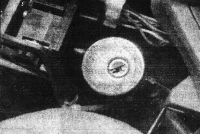
6.3. Disconnect the electrical wiring from the ignition switch.
Text provided by an online resource [renaultbook]
If necessary, lower the driver's side instrument panel to gain access.
4. Insert the ignition key into the switch and turn it to position "M" (or "3").
5. At the rear of the switch, use a socket wrench to loosen the countersunk screw securing the switch assembly to the steering column (see illustration).
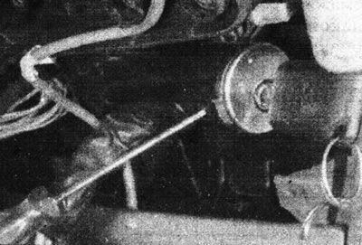
6.5. Loosen the ignition switch mounting screw.
6. Using a screwdriver, press the retaining clip at the bottom of the switch, then separate the assembly from the steering column. Route the wiring through the steering column (see illustrations).
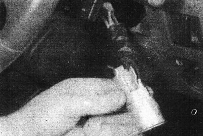
6.6a. Press the ignition switch release.
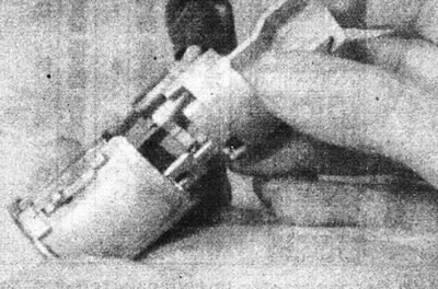
6.6b. Remove the ignition switch.
7. To separate the switch from the lock assembly, unscrew the two mounting screws on the back of the housing and remove the back cover. Now the switch can be removed from the lock (see illustrations).
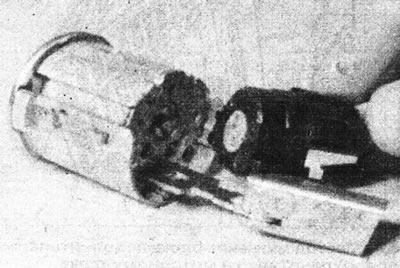
6.7a. Remove the rear ignition switch cover...
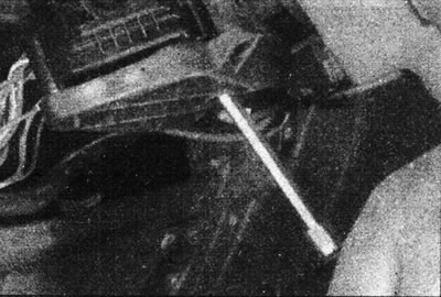
6.7b....and remove the switch from the lock.
Installation
8. Install in reverse order, paying attention to the following.
9. When installing the switch into the lock assembly, make sure that the locking tabs on the lock fit into the slots in the switch. Please note that the switch can only be installed in one position.
10. Properly route the switch wiring as marked before removal.
Combination light/turn signal/horn switch
Removal
11. Disconnect the negative cable from the battery.
12. Remove the steering column shaft housings.
13. Unscrew the two mounting screws from the bottom and remove the switch from the steering column (see illustration).
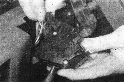
6.13. Unscrew the mounting screws...
14. Disconnect the connectors and remove the switch (see illustration).
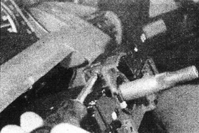
6.14. ...then disconnect the connectors and remove the combination switch.
Installation
15. Install in reverse order.
Windscreen washer/wiper switch
16. Proceed as described for the combination light/indicator/horn switch.
Combination switch block
Removal
17. Remove the steering wheel as described in Section 10.
18. Proceed as described in points 11 and 12.
19. Disconnect the connectors from the switches.
20. Where necessary, slide the car radio remote switch off the bracket on the combination switch.
21. Loosen the clamp screw at the top of the switch, then remove the assembly from the steering column (see illustrations).
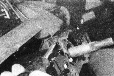
6.21a. Loosen the clamp screw...
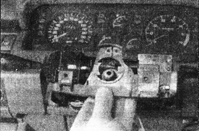
6.21b....and remove the combination switch assembly.
Installation
22. Install in reverse order. Install the steering wheel as described in Section 10.
Car radio remote control switch
Removal
23. Disconnect the negative cable from the battery.
24. Remove the car radio. Disconnect the wiring from the remote switch (see illustration).
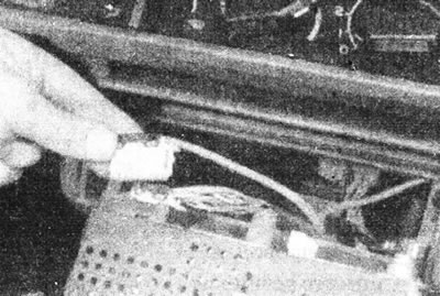
6.24. Disconnect the remote switch wiring from the car radio.
25. Remove the steering column covers.
26. Slide the switch off the bracket on the combination switch assembly (see illustration).
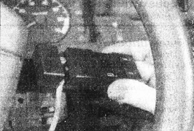
6.26. Remove the car radio remote control switch.
27. Feed the wiring through the panel and remove the switch.
Installation
28. Install in reverse order, paying attention to the following.
29. Install the car radio.
30. Make sure the wiring is routed as noted during removal.
31. Do not fully tighten the switch screw until the steering column covers are installed.
Switches in the dashboard
Removal
32. Disconnect the negative cable from the battery.
33. Using two screwdrivers, carefully pry the switch off the panel, being careful not to damage the trim (see illustration).
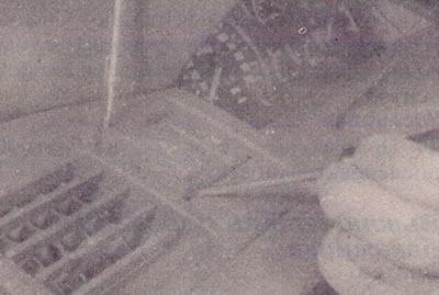
6.33. Remove the switch from the instrument panel.
34. Remove the switch from the panel and disconnect the wiring.
Installation
35. Install in reverse order.
Headlight beam direction control
36. Look Chapter 11.
Instrument cluster dimmer
Removal
37. Disconnect the negative cable from the battery.
38. Using a screwdriver, carefully pry the regulator away from the panel, being careful not to damage the trim (see illustration).
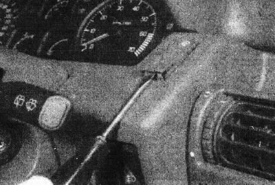
6.38. Press the dimmer switch out of the panel...
39. Remove the regulator from the panel and disconnect the electrical wiring (see illustration).
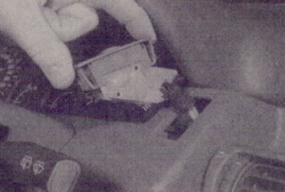
6.39. ...then remove it and disconnect the electrical wiring.
Installation
40. Install in reverse order.
Central locking control switches
41. See Section 11, Chapter 16.
Power window control switches
42. See Section 11, Chapter 17.
Interior light switches
Removal
43. The switches are installed in the front door pillars.
44. Disconnect the negative cable from the battery.
45. Remove the rubber cover from the switch (see illustration).
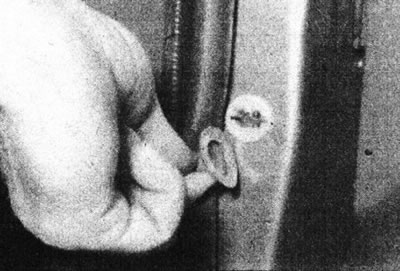
6.45. Remove the rubber cover from the interior light switch...
46. Carefully separate the switch from the door post and disconnect the electrical wiring from it (see illustration).
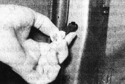
6.46. ...then remove the switch from the door pillar.
Then, make sure that the electrical wiring does not fall inside the rack, secure it with adhesive tape.
Installation
47. Install in reverse order.
Trunk light switch
Removal
48. Disconnect the negative cable from the battery.
49. Open the trunk door. Remove the trim on the right side of the trunk to access the switch.
50. Disconnect the wiring connector from the switch (see illustration).
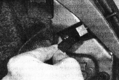
6.50. Disconnect the wiring from the trunk light switch.
51. Push out and remove the switch (see illustration).
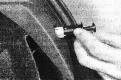
6.51. Remove the trunk light switch.
Installation
52. Install in reverse order.
Glove compartment light switch
53. The switch is mounted in the locking pin of the glove compartment lock
Map reading light switch
54. The switch is built into the hatch control panel and cannot be removed separately.