
Diesel vehicles have only the fuel gauge sensor in the fuel tank. The fuel supply for these engines is performed by high pressure fuel pump.
With a decrease in the fuel level in the tank, the sensor float lowers.
This simultaneously increases the resistance of the sensor, which is connected to the float by a sliding contact. Due to the increase in resistance, the voltage on the instrument panel decreases and the arrow of the fuel gauge deviates to the side with the designation «empty».
If the float drops even lower, then at a certain point the signal contact is closed and the orange signal light on the fuel gauge lights up.
Removing
Attention! Ensure adequate ventilation of the workplace. Fuel vapors are poisonous. No open fire! No smoking! Fire hazard! Keep a fire extinguisher ready!
Attention! To remove the fuel gauge sensor, the fuel tank must be empty. To do this, the existing fuel supply should either be used up and not refueled, or drained into a suitable container. This procedure should be done outdoors if possible.
1. Disconnect the wire terminal «masses» (-) from the battery.
Attention! This deletes data from the memory devices, for example, the security code of the radio. Before disconnecting the battery, please read the chapter «Battery - removal and installation».
2. Fold back the rear seat and remove the round cover that covers the sensor.
3. Disconnect multi-contact sensor 1 (see illustration 4.3).
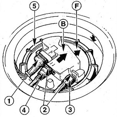
4.3 Disconnect multi-contact sensor 1. 2 - clamps; 3 - supply hose; 4 - return hose; 5 - union nut
4. Remove with pliers, eg Mot. 1265 facom (for diesel engines Mot. 1265-01) clips 2 with fuel hose connectors (see illustration 4.3).
5. Disconnect supply 3 and return 4 hoses using special pliers (see illustration 4.3). When disconnecting hoses, place a rag to collect escaping fuel. Hose fastenings are specially marked with paint so that the hoses cannot be mixed up during installation. The return hose is attached opposite arrow B. Arrow F points longitudinally to the rear (see illustration 4.3).
6. Carefully unscrew the union nut 5 by turning it to the left (see illustration). In workshops for this purpose, use the tool Mot. 1264-01FACOM. The nut can also be unscrewed using a wooden block, hitting it with a hammer (see illustration 4.6).
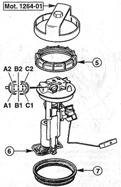
4.6 Assignment of the terminals of the multi-pin plug: 6 - sieve; 7 - gasket cover A1 - «weight» (-); A2 - signal light for fuel reserve in the tank; B1 - fuel reserve indicator; B2 - not used; C1 - (+) fuel pump; C2 - (-) fuel pump
Attention! When doing so, care must be taken to avoid sparking.
7. Lift the fuel gauge sensor up, tilt it to the side and remove it from the tank. Place a rag under it to prevent fuel from spilling.
Attention! Screw on the union nut if the sensor has been removed for several hours. This is necessary to prevent contamination from entering, which will subsequently complicate installation.
Checking the sensor for vehicles with a body «sedan»
8. Hold the removed transducer vertically by moving its float to the desired height (see table).
9. Measure the resistance at terminals A1 and A2. The values given in the table are indicative, so some deviation is allowed.
Installation
10. Make sure that the sieve 6 of the fuel pump is not dirty (see illustration 4.6). Clean it if necessary.
11. Check up a condition of a sealing lining 7 of a cover. If lagged porous or damaged; replace it.
12. Install the gauge and the fuel pump in place so that after fixing them, you can connect the fuel hoses. Make sure the mark F (see illustration 4.3) turned back.
13. Replace ring nut 5 (see illustration 4.6) and tighten it. The approximate tightening torque is 60 Nm. Tighten the nut with a wooden block, hitting it with a hammer. In this case, install the bar at different points of the nut.
14. Connect the fuel hoses, guided by the color marking and fix them in the couplings. No special tool is required for this.
15. Place clamps 2 on the hose couplings (see illustration 4.3).
16. Connect the multi-pin plug.
17. Close the hole with a cover and raise the rear seat.
18. Connect the wire terminal to the negative pole of the battery «masses» (-), set the clock and radio.