



2. In general, a conventional ignition system functions as follows. Low voltage current from the battery is supplied to the ignition coil, where it is converted into high voltage current. This voltage is sufficient to generate a powerful spark between the spark plug electrodes in the cylinder at a rate of many times per second under high pressure, provided that the ignition system is in good working order and all components are properly adjusted.
3. The ignition system consists of two separate circuits known as the low voltage (primary) circuit and the high voltage (secondary) circuit.
4. The low-voltage (primary) circuit includes: the battery, wiring to the ignition switch, wiring to the primary winding, the primary winding of the ignition coil, wiring from the primary winding to the contact plates of the breaker, and the capacitor in the distributor.
5. The high-voltage (secondary) circuit includes: the secondary winding of the ignition coil, the wire from the center of the ignition coil to the center of the distributor cap, the distributor rotor, the spark plug wires, and the spark plugs.
6. The ignition system works as follows. The low voltage current from the battery is converted into high voltage current in the ignition coil by closing and opening the contact plates of the breaker in the low voltage circuit. High voltage current is then supplied through a contact in the center of the distributor cap to the rotor. The rotor rotates inside the distributor cap, and each time it passes one of the four tips in the cap. The opening and closing of the contact plates of the breaker causes a high voltage current to flow through the gap between the distributor rotor and the tip in the cap for the corresponding spark plug, and then through the wire to the spark plug, where a spark finally jumps across the gap between the two electrodes of the spark plug.
7. For the engine to operate properly, the spark to ignite the fuel-air mixture in the combustion chamber must occur at a strictly defined moment in time relative to the engine speed and load. The ignition timing angle is automatically adjusted depending on the load and engine speed.
8. Ignition timing is controlled by mechanical and vacuum systems. The mechanical regulator mechanism consists of two weights that move out of the central shaft of the distributor under the action of centrifugal force when the engine speed increases. As they move outward, they rotate the cam relative to the distributor shaft, changing the ignition timing. The weights are held in their original position by two weak springs, the tension of these springs significantly affects the correctness of the lead angle adjustment.
9. The vacuum regulator consists of a diaphragm, one side of which is connected through a small-section pipe to the carburetor, and the other to the contact breaker plate. The degree of vacuum in the manifold and carburetor depends on the engine speed and the opening of the throttle valve, and causes the diaphragm to move, the contact breaker plate rotates and changes the ignition timing.
10. The auxiliary transistor block frees the breaker contacts from transmitting the full primary current, resulting in an extended service life and increased system reliability. The breaker contacts are used only to switch the transistor, which carries the full primary current.
11. On some models, the unit has two sockets: the upper one is for normal mode using transistor amplification, and the lower one is for emergency mode, bypassing the transistor unit (conventional ignition system with interrupter). The wiring connector is simply moved from one socket to another. In other models, the block is non-separable, without two sockets.
12. The transistor works as follows (section F in the illustration).
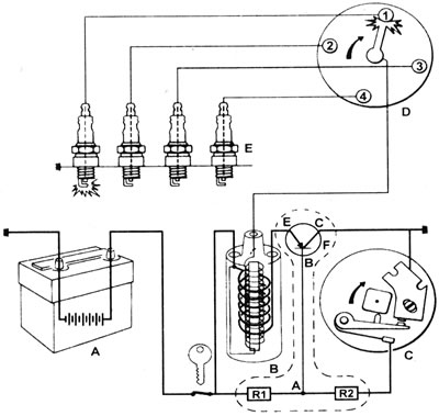
1.12. Schematic diagram of a transistor ignition system with an interrupter: A - Battery; B - Ignition coil; C - Contact breaker; D - Distributor cover and rotor; E - Spark plugs; F - Transistor block.
When the breaker contacts are open, the potential at the base (B) and emitter (E) of the transistor is the same and therefore no current flows through it.
When the contacts close, a negative potential appears at the base (B) due to the voltage drop at point (A), and current begins to flow through the transistor's collector (C). Resistors R1 and R2 in the circuit provide a low control voltage, which also significantly increases the lifespan of the breaker contacts. When the contacts open again, the voltage increases at point (A) and at the base (B), and the transistor turns off.