
Removing
1. Mark the position of the front wheels on the hub with paint. This will allow the assembly to set the balanced wheel in its original position.
2. Loosen the wheel nuts. The vehicle must be on wheels during this operation.
3. Place the vehicle on jack stands and remove the front wheels.
4. Unscrew a nut of a finger of a spherical support of a tip of cross-section steering draft.
5. Press the tie rod ball joint pin out of the steering knuckle using a puller, such as RENAULTT.Av.478 or HAZET 779 (see illustration).

20.5 Press the tie rod ball pin out of the steering knuckle using a puller, e.g. RENAULTT.Av.478 nnnHAZET779
6. Loosen the lock nut E and unscrew the tip from the tie rod, holding the rod by the hexagon P with a wrench from turning (see illustration).
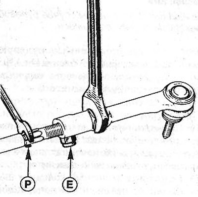
20.6 Loosen the lock nut E and unscrew the tip from the tie rod, holding the tie rod by the hexagon with a wrench from turning
Attention! When unscrewing the tip, count the number of turns and write them down. This value will be needed when installing the tip and adjusting the camber and toe.
7. Remove the cuff from the gear rack, loosening the clamp before this and removing it from the cuff.
8. Use the special tool to keep the rack from turning when unscrewing the tie rod. In workshops, for this purpose, depending on the model of the steering mechanism, they use the appropriate tool. If the vehicle is fitted with an SM1 steering gear, use tool Dir. 1306. When equipped with a TRW steering gear -Dir.1306 -01 (see illustration). The device is put on the gear rack and fastened with bolts A and rests on the steering gear with a lever (see illustration 19.8).

20.8 Use the special tool to keep the rack from turning when unscrewing the tie rod
Attention! In any case, the gear rack must be kept from turning. Otherwise, the steering mechanism will be damaged.
9. Unscrew the tie rod using tool Dir. 1305 at the point of attachment of the axle joint (see illustration) and take it off.

20.9 Unscrew the tie rod using tool Dir.1305 at the location of the axle joint
Examination
10. Check the position of the tie rod end stroke. If the tip moves too easily or has significant play, then replace the tip.
11. Inspect the protective cap of the ball joint of the tie rod end and make sure that it is not damaged and that grease does not leak from under it. If the cap is damaged, the tie rod end must be replaced with a new one.
12. Examine the cuff of the gear rack. In the presence of traces of porosity of rubber, cracks or cuts replace a cuff.
Installation
13. Use a M12x1.00 tap to clean the threaded hole on the end of the rack to remove any remaining protective grease.
14. Vehicles with SMI steering gear. Be sure to replace parts 2 (thrust and locking gaskets 3) for new ones. When installing the thrust washer, the grooves on it must match the flats B on the rack 4 (see illustration).

20.14 Mandatory replacement of parts 2 (thrust and locking gaskets 3) for new
Attention! The TRW steering gear does not have parts 2.
15. Lubricate the threads of the axle joint shank 1 with LOCTITE FRENBLOC protective grease. Do not apply large amounts of lubricant because it will clog the drain hole.
16. Screw the axle joint shank into the rack using the RENAULT special tool and tighten it. Shank tightening torques:
- steering gear firm SMI - 50 Nm;
- steering gear firm TR IV - 80 Nm.
When tightening the shank, keep the rack from turning. Otherwise, it will be damaged.
17. Remove the special tool from the rack.
18. Grease a surface of a prileganiye of a cuff on an axial hinge with a thin layer of greasing and establish a new cuff.
19. Align the wheels, setting them in the direction of travel in a straight line to equalize the pressure inside both cuffs of the steering mechanism. Equalize cuff pressure if necessary. It should not be drawn in due to less pressure.
20. Secure the cuff with a new collar.
21. Screw the tip onto the tie rod with the same number of turns as it was during removal, and fix it with a lock nut. Locknut tightening torque 20 Nm.
22. Insert the tip ball joint pin into the lever hole on the steering knuckle and screw a new self-locking nut onto the pin. Nut tightening torque 35 Nm.
23. Replace the wheel, guided by the marks made during removal and secure it with bolts
24. Lower the vehicle onto the wheels and tighten the wheel bolts in a criss-cross pattern to 90 Nm.
25. Check the camber and wheel alignment. Adjust them if necessary.